Molding & Casting - Machinable Wax on Modela

This week's assignment is comprised of a four-part process to fabricate a 3D object:
1. Use a CNC mill to digitally fabricate a mold out of wax
2. Create a negative of the mold with a flexible rubber
3. Use the flexible rubber as the mold for the final part
4. Cast the Final Part
Review Neil's class page
Contents:
- Step 1. Create a Positive Mold Model
- Step 2: Mill the Wax on the Modella
- Step 3: Make a Mold from the Wax
- Step 4: Cast Final Object
- Tips and Tricks
Step 1. Create a Positive Mold Model
Create a model of the final part you want to make. You can create a 2D or a 3D file as a starting point for your mold.
General Tips:
- MAKE SURE YOU ACTUALLY DESIGN A POSITIVE MOLD!
- No Undercuts - the Modella / Shopbot plunges straight down.
- Flat bottom single sided molds will work best if you are casting in flexible silicone rubber (OOMOO), as the OOMOO tends to bow out at the sides. Make thick walls if using a two sided mold.
3D Models
If you create a 3D file, you need to decide if you want to make a 1 or a 2 part mold.
General 3D Model Tips
- Your model must be exported as a binary .stl file. Make sure that the file extension is lowercase (.stl) NOT uppercase (.STL). The Fab Modules will not recognize an uppercase extension.
3D 1-Part Molds
- If you want to create a 1 part mold - design a 3D file with a flat back side.
- The flat back side can rest on the ground in the final cast.
3D 1-Part Molds Examples (from HTMAA 2011):
2-Part Mold Tips
- You will need to make two models; one for each side of the mold.
- It is also possible to do more than 2 part molds, it just takes more design work and planning.
- Include registration keys / marks.
- Registration marks are used to fit the parts of the mold together - usually they're half-spheres / cylinders, where one side has the stub and the other has the indentation.
- Make sure to design a pour spout and sprues.
- Model each side separately and include registration marks, as well as a vent.
- Make it AS BIG AS POSSIBLE! It will make your life easier when you need to pour and then you can vent out of the same hole you pour in (you can make separate holes too if you need to).
- Place the vent on an axis of symmetry so that you don't also have to worry about lining up the vents when you make the molds.
- Place the vent at the top of the part! You don't want to vent out of the bottom of the part because then material will just pour out!
- Make sure there are no parts of the mold that will obstruct the path of the Hydrostone (or whatever material you are using) as you pour it into the mold - you want to be sure that you can completely fill the mold, which is harder if you have bits sticking up in the path of the HydroStone.
3D 2-Part Molds Examples (from HTMAA 2011):
- Lingin Yao: Eyeglasses
- Josh Ingram: Robots
- Shaul Goldklang: Escher Tiling
- Kristopher dos Santos: Mini Pumpkins
- Check out the HTMAA 2011 Class index for more examples
2D Models (PNG Images)
2D 1-Part Molds
- To make a one-part 2-dimesional relief mold (the simplest thing to do for this assignment), you create a image in a drawing program (The Gimp, Photoshop, Inkscape).
- Your image must be grayscale.
- Create your image at a high resolution 500 dpi.
- You must save or export the file as a .png.
- The fab modules read colors the .png image as a depth.
- Black = bottom of the part
- White = top of the part
- You will define the height of the model and the bottom and the top settings for milling placement in the wax in the fab modules.
- Shades of Grey = somewhere in between the heights you define in the Fab Modules for black and white.
- For example 50% grey is halfway between black and white, if you set the bottom of your model as 3mm, then 50% grey = 1.5mm deep.
- We have experienced some resizing / changing from grayscale to color, etc when exporting PNGs.
Make sure to open your file up in The Gimp to check resolution, color mode (grayscale) and image size before opening the image up in the Fab Modules. - If you experience any errors or problems with double check your image. You may need to add a white border around the image as a last resort.
2D 1-Part Mold Examples:
Tools Relief Example:

Step 2: Mill the Wax on the Modella
Selecting The Appropate Bit
- In the computer model / file you created, use a measuring tool (or estimate) the spacing between the parts or detail where you want the bit to pass through.
- You need to make sure that the bit is small enough to cut out the detail in your model. You can preview the toolpath in the Fab Modules before you cut it - see steps below -"Fab Modules Workflow for Wax (General Setup / Steps) "
- Also pay attention to the depth of your model:
- Smaller diameter bits have shorter cutting depths.
- Larger diameter bits (1/8") - standard size used in the fab modules - has a longer shank and can reach deeper into the wax.
- For curvy models - use ballnose bits
- For mostly flat parts / straight angles - use endmill bits
Bit Diameters in Milimeters:
| Bit Diameter | Bit Diameter (MM) | Max Cutting Depth | Max Plunging Depth |
| 1/16 | 1.5875 | measure cuttng depth | measure shank depth |
| 1/8 | 3.175 | measure cuttng depth | measure shank depth |
| 1/8 (long) | 3.175 | measure cuttng depth | measure shank depth |
Setting Up Your Wax For Milling
Secure your wax to the Modela
- Use double sided tape to adhere your wax to the Modela platform.
- Double sided tape is not enough by itself!
- Use hot glue along the sides of the bar to keep the wax comming loose from the Modela.
General Fab Modules Workflow for Wax (General Setup / Steps)
- Open terminal and type "fab" to open the Fab Modules.
- Choose the appropiate file type:
- If you are using a PNG: select PNG to Roland Modela

- if you are using a STL: select STL to Roland Modela

- Insert the appropiate bit into the Modela. The default size is 1/8".
- Position the bit onto the wax using the "move to xmin, ymin" button (just like we did for milling circuit boards.)

- Zero out your Z axis to the top of the wax. Stop when a few shavings of wax come up.
- Set up your rough cut settings:
- see the chart below for settings descriptions.
- see the workflow screenshots for STL and PNG specific info,
- If the speed is not at 20 - change it to 20, we want the machine moving as fast as possible.
- Execute your rough cut.
- DO NOT turn the machine off and on between cuts! We want to retain the Z axis zero setting.
- If you do turn the machine off or need to change to a smaller bit, use the xmin, ymin move command to move back to the same starting origin, then zero the bit out so it is close to the surface of the wax, then loosen the set screws and drop it down until it touches the surface of the wax. Then you will know it is zeroed properly.
- Set up the finishing toolpath
- see the chart below for settings descriptions.
- see the workflow screenshots for STL and PNG specific info.
- If the speed is not at 20 - change it to 20.
- Execute the finishing toolpath.
- Remove the wax from the machine.
Fab Modules Settings (Both Rough and Finishing Cuts)
| What the Setting Controls: | Rough Cut Defaults | Finishing Cut Defaults | |
| diameter |
|
The default is: 1/8" or 3.175mm | The default is: 1/8" or 3.175mm |
| offset |
|
The default setting removes all material around your model: -1 | The default is 1. Change this to -1 if you want the box around your model to get a finishing path applied to it. |
| overlap |
|
The default is: 0.25 | The default is: 0.5 |
| speed |
|
STL: The default is 20 If using a PNG - make sure to change this to 20. |
STL: The default is 20 If using a PNG - make sure to change this to 20. |
in 3D Setting Windows |
|||
| top height |
|
The default setting is blank. I recommend you start at -1 mm. |
The default setting is blank. I recommend you start at -1 mm. |
| bottom height |
|
You need to set this manually. | You need to set this manually. |
| cut depth |
|
The default settings should be fine for a rough cut. | The default settings should be fine. |
| path |
|
STL: The default selection is the xy path PNG: The default selection is the z path |
STL: The default selection is the xz finish and yz finish paths PNG: The default selection is the xz finish and yz finish paths |
Workflow for PNG to Modela
- Open Fab Modules (from terminal > type "fab)
- Select PNG to Roland Modela
- Click "load PNG" to load your image. The PNG will load in the window.

- Select "rough cut" from the drop down menu.

- The interface will populate with the default settings for a rough cut using a 1/8" bit. If you are not using a 1/8" bit change the diameter. The bit size must be in milimeters. The other settings should be fine.

- You need to change the 3D settings to work for your model. Click the 3D settings button and a new menu will pop up.

- The top height setting tells the machine where to start milling the top of your file.
- Since the blocks of wax have an uneven top surface, it is wise to start at least -1 mm below the surface, mabye more.
- The top height value must be 0 or negative. A positive value will result in a error.
- The bottom height setting is the how tall / deep you want your model to be. This must also be a negative number or you will get an error.
- Example settings shown for the tools mold file.

- Close the 3D settings window and click "make path"

- You can see from the toolpath generated that this bit is a little too big to get all the detail in this model. Use a smaller bit diameter and generate the toolpath again. You can do this to preview the path. After you can see the detail, you can put the appropiate bit in the Modela.
- Position the bit onto the wax using the "move to xmin, ymin" button (just like we did for milling circuit boards.)
- Zero out your Z axis to the top of the wax. Stop when a few shavings of wax come up.
- Click "make rml" and then send it to the machine.
- After the job completes, create a finishing pass - select "finishing pass" from the dropdown.
- Do not turn off the machine.
- You do not need to import / make a .png again.
- The machine will retain the Z axis zero setting from the previous job.
- If you changed the bit diameter, make sure to change it again.
- follow the steps above for the finishing pass.
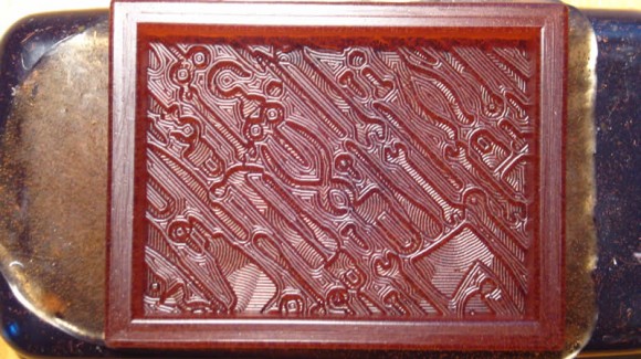
Milled wax

Workflow for STL to Modela
- Open Fab Modules (from terminal > type "fab)
- Select STL to Roland Modela
- A new window will open. Just like milling circuit boards, work from left to right. Select "Load STL"

- No image will load - just text with the name of the file and the number of triangles.

- Then click "make png". A PNG representation of your STL will appear. If your model is not showing up, try changing the "side" axis. This depends on how you set up your model.

- First do a rough cut. Select your settings from the dropdown menu for the units in your STL, (mm or inches).

- The default settings will load for a rough cut with a 1/8" bit in milimeters. If you want to use a smaller sized bit, you can change this value. Make sure the value is in milimeters.

- Next you need to adjust the 3D settings. Click on the "3D settings" button. A new window will pop up.

- Use the settings chart above to adjust the settings. The top height of the wax is uneven, so make the top height at least -1 mm or more to make sure the top of the wax is machined away. The bottom height should be the height of your STL model. When you are finished, click "close".
- Next - click "make path" to generate the toolpath. You can click "view path" to view the path in greater detail in occular.

- Next, make put the Modela in "view" mode and move the xmin and ymin so that the bit is over the wax.
- Manually zero out the Z axis until a little bit of wax comes up.
- Click "make rml"
- Then send the job to the machine.
- After the job completes, create a finishing pass - select "finishing pass" from the dropdown.
- Do not turn off the machine.
- You do not need to import / make a .png again.
- The machine will retain the Z axis zero setting from the previous job.
- If you do turn the machine off or need to change to a smaller bit, use the xmin, ymin move command to move back to the same starting origin, then zero the bit out so it is close to the surface of the wax, then loosen the set screws and drop it down until it touches the surface of the wax. Then you will know it is zeroed properly.
- If you changed the origional bit diameter, for the rough cut, make sure to change it again. (it will defult back to 1/8" when you change to the finishing cut settings.)
- Follow the steps above to set up and exceute the finishing pass using the finishing pass settings.
Step 3: Make a Mold from the Wax
Mix silicone and pour into the wax mold - this will form a NEGATIVE mold with POSITIVE space
Oomoo
- Equal parts A&B by volume
- Mix, mix, mix
- Demold in 75 minutes
Other Molding types - read the instructions on the package
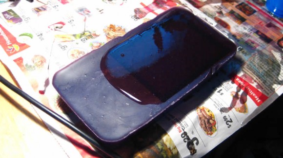
Tools Mold in Urathane Rubber (OOMOO mold will be blue)
Step 4: Cast Final Object
Fill the silicone mold with HydroStone to make the final POSITIVE piece.
Hydrostone
- Mixing instructions: http://plaster.com/mixing.html
SmoothCast 305 - Plastic - read the instructions for the material (on the box)- use mold release if casting in urathane rubber, if using OOMOO, you do not need a mold release.
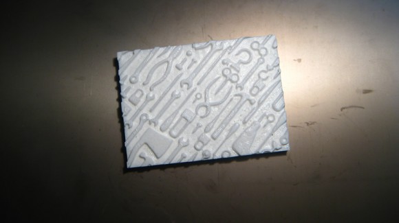
Chocolate - coming soon. Final Cast in SmoothCast 305 (white plastic)
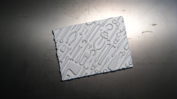
Final Cast in Hydrostone
Tips and Tricks
- Don't forget that complex geometry will generate complex tool paths. Complex tool paths can take a very long time.
- It seems that bubbles form at right angles. Keep this in mind during design. Also, lots of 'local minimum' (aka lots of different dips and valleys) probably lend themselves to bubbles. Be aware!
- The walls of a flexible mold (approx 0.3" thick) can bow outward when the material is poured in and can this give your final piece slightly rounded edges. If you are trying to assemble multiple pieces and tolerances are important, you might want to use a very thick flexible mold wall or consider other options.
- .stl not .STL
