FabISP: Electronics Production

What is the FabISP?
The FabISP is an in-system programmer for AVR microcontrollers, designed for production within a FabLab. It allows you to program the microcontrollers on other boards you make.
Assignment
The Electronics Production assignment is to mill the board, stuff it with components and program it. We will be using these programmers through the semester to program the other boards we create.
Genology
The geneology of the FabISP design is interesting in its own right; Neil's FabISP is based on David Mellis's FabISP which is based on Limor's USBTinyISP which is based on Dick Streefland's USBTiny.
Download the Board Files and Mill the Board
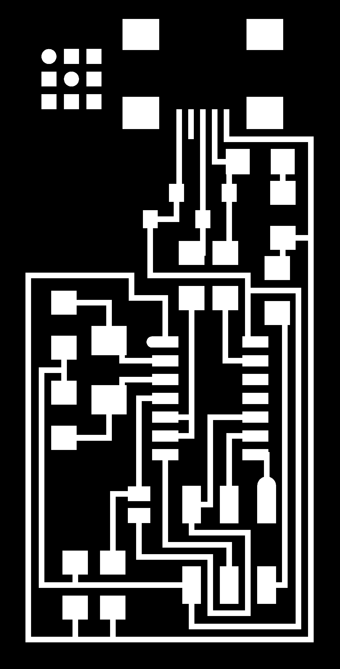
Circuit Board Traces
- Download the traces png.
- Mill using the fab modules and a 1/64" bit.
Board Outline
- Download the outline png.
- Mill using the fab modules and a 1/32" bit.
Milled FabISP Board

Stuff Board
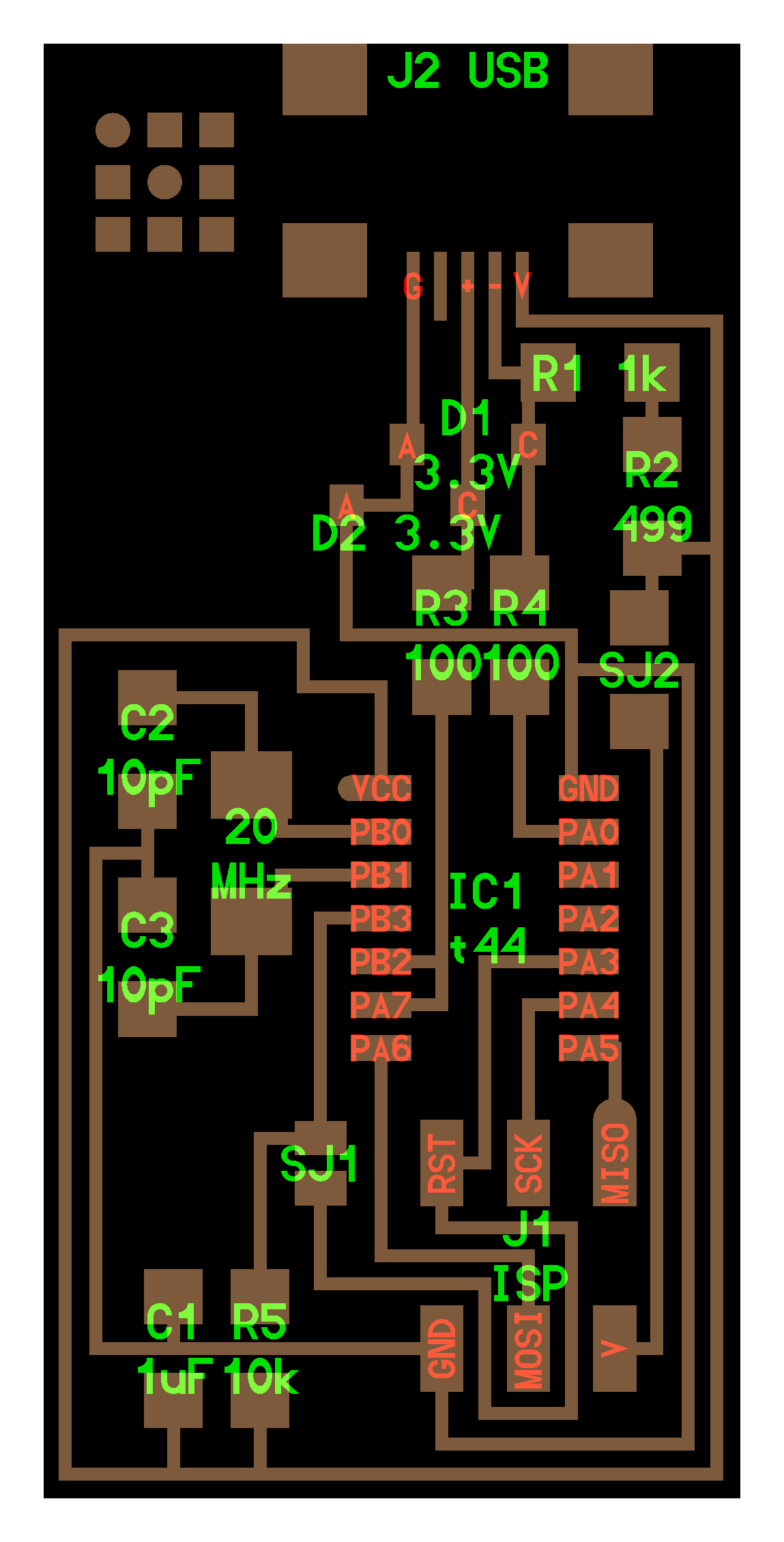
Download the FabISP labeled board diagram so that you can see what components you need to and where to place them on the board.
Solder the components to the board using a soldering iron and solder (or solder paste and then baking.)
Components
These are the all the parts you need to build the board.
|
|
Mini USB Header
- Solder the mini USB header first. This is the most difficult part and if you are going to destroy the board, you are going to do it here.
- J2 USB is the mini USB header
- Solder with a blob, then wick solder away with desoldering braid.
Microcontroller
- Solder the microcontroller second.
- "IC1 t44" in the diagram is an attiny44a chip.
- There is a little circle on the chip that should be facing to the top left if your board is oriented in the same direction as Neil's diagram.
- I have marked the circle on the pinout diagram below
- Here is the datasheet for the attiny44.

Crystal
- Marked as "20 MHz" on board diagram.
- Tin the pads first, then place the component on top.
- Hold component down with tweezers, the reflow solder at either end.
- NOTE: crystals do not have polarity, orientation does not matter.
Diodes
- Diodes have polarity the "C" or cathode end is marked with a tiny line.
- Place the side with the line on it over the "C" side pad in the diagram.
- You may need a magnifing glass.
- NOTE: it is helpful to solder the 1K resistor first, otherwise it is hard to get to after you have soldered the diodes.
Resistors
- Components marked with an "R" (R1, R2, etc) are resistors.
- Here is a handy SMD (surface mount) resistor code calculator.
- NOTE: resistors do not have polarity, orientation does not matter.
| Diagram Label |
Component Value | Part Label |
| R1 | 1K ohm | 1001 |
| R2 | 499 ohm | 4990 |
| R3, R4 | 100 ohm | 1000 |
| R5 | 10K ohm | 1002 |
Capacitors
- Components marked with a "C" (C1, C2, etc) are capacitors.
- Capacitors are not marked, be careful not to mix them up.
- NOTE: capacitors do not have polarity, orientation does not matter.
| Diagram Label |
Component Value | Part Label |
| C1 | 1uf | unmarked |
| C2 | 10pf | unmarked |
| C3 | 10pf | unmarked |
Jumpers
- The components marked SJ1 and SJ2 are solder jumpers.
- SJ1 can be bridged with solder.
- Put a 0 ohm resistor over SJ2 on this board
6 pin programming header
- The components marked J1 ISP is the 6 pin programming header.
- Orientation does not matter.
"Smoke Test"
Plug the FabISP into your computer via the mini USB cable.- If you get an error message from your computer that the board is drawing too much power and that the computer is shutting down the USB port.
- You have a short somewhere on your board. See (Troubleshooting Short Circuits).
If you do not recieve any messges, proceed to "Install the necessary software for AVR programming."
Troubleshooting Short Circuits:
- First, do a visual inspection of the board and reflow any solder joints that look cold (not shiny and smooth).
- Then, get out your multimeter and check all the connections to make sure that:
- power and ground are not connected
- there is not a short on the power line.
- Common problem areas on the FabISP are:
- the pins on the 6-pin programming header are connected to each other.
- the tiny pins on the front of the mini USB header are connected to each other.
- none of these pins should be connected.
- use your meter to determine which pins are connected.
- use flux and desoldering braid to remove the excess solder and disconnect the pins.


